Loading component...
Contact us to create your custom solution
Call us at: 704-859-2723 or fill out the form below.
Call us at: 704-859-2723 or fill out the form below.
The Gas Turbine inlet filter system and the turbine itself can be adverseley affected when freezing temperatures combine with high moisture content. Damaging effects happen in a very short time, could be long-lasting and expensive in terms of operational effectiveness and maintenance costs.
Ice can be ingested into the turbine, structurally compromising the system. Increases in differential pressure across the filters and total vacuum pressure at the inlet to the turbine reduce airflow.
Ultimately, the additional negative pressure reduces the available output of the turbine, affecting plant revenue. If plugging of filters is excessive and the maximum allowable differential pressure across filters is reached, they can be damaged permanently.
Complete turbine shutdowns are possible. Replacement filters may not be immediately available, requiring prolonged downtime and loss of revenue plus unplanned maintenance labor costs.
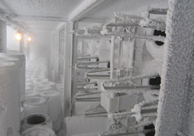
Figure 1: Ice clogged filters have been removed to allow some air to pass unfiltered
Ice can form inside the inlet system even when the outdoor temperature is not freezing. When the air enters the inlet filter system, it speeds up as it passes through the filter house and inlet duct and silencer due to a venturi effect.
This velocity increase causes a decrease in the temperature of the air and condensation of water vapor in the air, possibly forming ice at the compressor inlet.
Some turbines use inlet guide vanes to restrict airflow into the turbine and allow running at partial load. The restriction of the space between guide vanes as they are closed down can cause higher velocities and ice formation. If the ice dislodges during operation and impacts the first r second row compressor blades, they can be damaged.
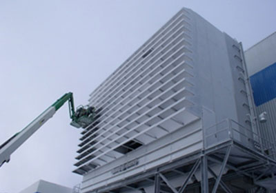
Figure 2: Operators attempting to remove snow and ice
Plugged filters from ice or snow have limited remedies. Operators can remove some filters to relieve pressure to the turbine, but this may leave risk for foreign material ingestion and possible further damage to the turbine. Or, if ice or snow has only collected on the first stage prefilters, removing only the prefilters may allow continued operation. Yet now the expensive filters are exposed.
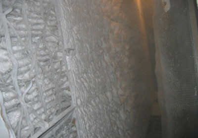
Figure 3: Snow and ice has built up heavily between static filter pleats and is not easily removed
Sometimes, operators attempt to brush off snow and ice from the filters using brooms, or remove filters and try to shake them off. This is usually not effective since ice can form within the filter media itself or between pleated media, not just on the surface. There is a very real risk of damaging filters using these methods.
Alternatively, operators might spray filters with de-icing fluid. Air filters are not normally designed for direct contact with liquid chemicals, so there is real risk of permanent damage. Ingestion of the de-icing fluid into the turbine can cause damage there. Fluid on the ground is a potential environmental contaminant.
Prevent the filters from freezing over in the first place or prevent the formation of ice at the turbine compressor inlet by providing inlet air heating.
Here are some options:
If only the compressor inlet ‘bell mouth’ area is to be protected, the heat can be injected in the inlet duct downstream of the main combustion air silencer and far downstream of the inlet filters. A solution like this generally results in a lower initial capital cost for the heating system. But, injecting heat downstream of the filters does nothing to prevent filters from freezing over.
Injecting heat upstream of the filters generally helps both to protect the filters and prevent ice at the compressor inlet bell mouth, but the capital cost of the solution is higher.
To prevent ice formation due to the increase in air velocity in the inlet system, the typical recommended design value for inlet air temperature rise is about 12 degrees F (8 degrees C).
The goal is to reduce the relative humidity in the incoming air stream to about 68% RH so that condensation cannot occur and ice cannot form as the combustion air speeds up and cools as it flows through the filter house and inlet duct.
The operator may decide a higher heat load is required based on ingested snow, ice or cooling tower plumes.
If the inlet heating system is to provide enough heat to melt snow or ice that is ingested into the inlet and captured on filters, this greatly increases the heat load since the latent heat of fusion of water is much more than the heat required to simply raise the temperature of the incoming air.
The mass flow rate of ingested snow or ice must be estimated. It is often difficult to provide enough heat to melt all the ingested snow and ice. Design compromises are often made to limit capability only to melting partial or smaller loads.
In general, a value of 0.2 g/m3 of air adds about 10% heat load. Pressure drop on the combustion air flow path and noise are other factors to consider in the heating system design and may impact the choice of the heat source.
Compressor bleed air heating systems have very low combustion air pressure drop. But compressor bleed systems do add noise. Typical self-generating noise is 85 dBA SPL @ 1 meter. Silencers and other options are available if lower noise levels are needed.
Compressor bleed systems inherently reduce the available turbine power output since a significant portion of the total combustion air is not available for combustion.
The turbine OEM must be consulted to determine the maximum allowable bleed air and the resultant reduction in turbine output. The application of heating coils will add some measurable pressure drop to the combustion airflow path and this will result in some loss of turbine power output.
Using heating coils also requires additional piping for the return side of the fluid as well as re-circulation pumps. If steam is used, the condensate must be addressed. Pressure drop of glycol coils is likely to be higher than steam coils.
This is the most common type of inlet heating system. It uses a portion of the combustion air, bled off from the turbine compressor section which has been self-heated due to compression. The air is removed from the compressor at a piping connection on the compressor casing and recirculated back to the main inlet airflow.
This air from the compressor may be in the range of 500 F to 700 F and at 100 to 200 PSI depending on the turbine model and the stage of compression the air is bled from. The turbine OEM should be consulted first to confirm if a connection to the compressor casing exists and if the removal of some portion of the compressed inlet air is possible.It is known that multiple units of Siemens Westinghouse W501F (Siemens SGT5000F) SGT 8000H, GE 7FA, Mitsubishi M701F, M501G, and Alstom GT-11N2 model turbines have implemented compressor bleed air inlet heating systems.
The turbine OEMs have integrated such solutions as options to their base plant offerings in many cases.
System design requires the following inputs:
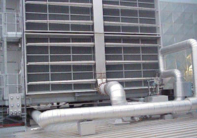
Figure 4: Example of a low pressure compressor bleed system. Routes low pressure hot air to face of system (note the thermal insulation on supply line). This system is capable of lowest self-noise but requires a large, centralized silencer (not shown) to attenuate noise of expansion.
Protecting the filters means first introducing the heat into the airflow upstream of the filters. This makes a larger heating array than if the only need is to keep ice from forming at the compressor inlet. In turn this also helps protect the inlet filters from freezing.
There are two options for dispersing the hot air in front of the filters: a high-pressure system or a low-pressure system. In the high-pressure system, the hot air is delivered nearly at the pressure it is bled off from the compressor.
The distribution system is constructed of piping. The dispersion of the air is accomplished with nozzles that reduce the pressure, attenuate noise and disperse the air radially from each nozzle. The number and placement of nozzles is determined in the detail design phase, but it is often over 100 on a large turbine inlet.
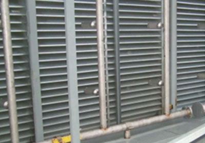
Figure 5: Example of a high pressure compressor bleed system. Pressure reducing, noise attenuating dispersion nozzles are mounted on the vertical pipe risers.
The low-pressure solution uses a pressure-reducing valve between the compressor bleed connection on the turbine and the filter inlet. The air can then be passed through lighter gauge ducting (but generally larger in cross section) and a central silencer is used to reduce the noise. Additional branch ducting is used on the inlet face with slots to disperse the hot air across the face of the inlet.
A heating system can be designed with steam or glycol circulated through traditional fin and tube coils mounted in the inlet air stream.
The disadvantage to using glycol as the fluid is that it introduces the need for either a heat exchanger or for a separate boiler to heat the fluid.
There is probably both added initial capital and operating cost for the boiler or heat exchanger and the fluid circulation pump and return piping. Fin and tube type coils are generally heavy, requiring that inlet filter supports be analyzed structurally to ensure the weight can be properly supported.
Steam has been used in some sites by piping steam from the HRSG back to steam coils mounted in the inlet.
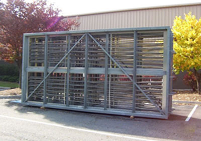
Figure 6: Example of a steam coil module completed at the factory ready for shipment to site
Nederman Pneumafil routinely provides engineered solutions to reduce costly repairs and unplanned downtime caused by cold temperatures and wet weather. In every opportunity the local site conditions are reviewed with the operator, the design goals are agreed, and a solution is developed. It must be noted that operators often want a guarantee as they justify their capital investment, that installing such a system will never shut down again due to snow and ice.
Such guarantees are very difficult to provide and the system performance is simply defined by how much heat is added. Mother nature and the weather are as unpredictable as ever and any occurrence of actual outdoor conditions outside the agreed upon design parameters can still possibly lead to downtime or reduced output.
However, a heating installation will absolutely reduce the amount of downtime or lost revenue compared to a system without such protection.
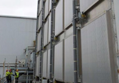
Figure 7: Example of heated inlet vanes with electrical resistance installed